Caisson & Drilled Shaft Foundations: Contractor's Field Guide | Projul
If you have been in the foundation business long enough, you know that not every site gives you the luxury of pouring a simple spread footing and calling it a day. When the soil report comes back showing 40 feet of clay sitting on top of limestone, or when the structural engineer tells you the column loads are north of 500 kips, you are looking at deep foundations. And for a lot of projects, that means caissons or drilled shafts.
This guide breaks down what you need to know about caisson and drilled shaft foundations, from selecting the right type to managing the installation process on site. Whether you are a GC coordinating a deep foundation subcontractor or a specialty contractor running the drill rig yourself, this information will help you plan better, avoid common problems, and keep your projects on track.
What Are Caissons and Drilled Shafts?
Caissons and drilled shafts are deep foundation elements that transfer structural loads through weak or unsuitable upper soils down to a competent bearing layer, whether that is bedrock, dense sand, or stiff clay. In today’s construction industry, most people use the terms interchangeably. You might hear “drilled shaft,” “drilled pier,” “bored pile,” or “caisson” depending on your region and the engineer you are working with. They all refer to the same basic concept: a large-diameter hole drilled into the ground, reinforced with steel, and filled with concrete.
The key distinction from driven piles is the installation method. Driven piles are hammered or vibrated into the ground as prefabricated elements. Drilled shafts are constructed in place by excavating the hole first and then building the foundation element inside it. This gives you more control over the final product and lets you verify soil conditions as you drill.
Shaft diameters typically range from 18 inches for light residential work up to 10 feet or more for bridge piers and heavy infrastructure. Depths vary just as much. A residential caisson might only go down 15 feet to hit bedrock, while a highway bridge shaft could extend 150 feet through soft alluvial deposits.
Before you start any deep foundation work, you need a solid geotechnical report that tells you what is in the ground, where the bearing layer sits, and what groundwater conditions to expect. Skipping or skimming the geotech report is one of the fastest ways to blow your budget on a drilled shaft project.
Types of Caisson and Drilled Shaft Foundations
Not all drilled shafts are created equal. The type you use depends on soil conditions, load requirements, and site access. Here are the main categories you will encounter:
Straight Shaft (End Bearing)
This is the most common type on commercial projects. You drill a cylindrical hole of uniform diameter down to the bearing layer, set the rebar cage, and pour concrete. The shaft carries load primarily through end bearing on rock or dense soil at the tip. If the geotech report shows a clear, well-defined bearing layer, this is usually your go-to option.
Straight Shaft (Friction)
In some soil profiles, there is no distinct rock layer at a reasonable depth. Instead, the shaft develops its capacity through friction between the concrete surface and the surrounding soil along the full length of the shaft. These are common in deep sand and stiff clay profiles. The engineer calculates the skin friction value for each soil layer and sizes the shaft accordingly.
Belled (Underreamed) Shaft
A belled shaft has a uniform diameter for most of its length but flares out at the bottom into a bell shape. The bell increases the bearing area at the tip, which lets you carry heavier loads without increasing the shaft diameter all the way up. Belling only works in cohesive soils like stiff clay that will hold their shape during excavation. You cannot bell in sand or below the water table without casing. These used to be more common but have fallen out of favor in many markets because of the added complexity and inspection challenges.
Rock Socketed Shaft
When the design calls for the shaft to extend into rock, you drill through the overburden soil and then socket into the rock formation. The socket depth and diameter depend on the rock quality and required capacity. Rock sockets add significant cost because drilling through rock is slower and harder on equipment, but they provide excellent load capacity and minimal settlement.
Cased Shaft
In unstable soils or when groundwater is present, you install a steel casing as you drill to keep the hole from collapsing. The casing can be temporary (pulled as concrete is placed) or permanent (left in place as part of the finished shaft). Casing adds cost and complexity, but it is non-negotiable when the ground will not stand up on its own. Knowing when you will need casing before you bid the job is critical for accurate estimating.
The Drilled Shaft Installation Process
Installation follows a general sequence, but the details vary based on site conditions, shaft size, and local practices. Here is the typical workflow:
Step 1: Layout and Setup
Survey crews locate each shaft center point based on the structural drawings. The drill rig is positioned over the first shaft location, and the operator verifies plumbness. On tight sites, crane mats or timber pads may be needed to support the rig and prevent it from sinking into soft ground.
Step 2: Drilling
The operator advances the auger or drilling tool into the ground, removing soil in lifts. In stable soils, the hole stays open on its own (dry method). In caving soils, the operator introduces drilling slurry (wet method) or advances casing to keep the hole stable. Each lift of spoils gets inspected informally by the operator and formally by the geotechnical inspector to confirm the soil matches what the boring logs predicted.
Step 3: Bottom Cleanout
Once the shaft reaches the design tip elevation, the bottom of the hole needs to be cleaned. Loose cuttings, slurry sediment, or disturbed soil at the base reduces end-bearing capacity. Cleaning tools or airlifts remove debris until the bottom meets the specification for cleanliness, usually less than half an inch of sediment for end-bearing shafts.
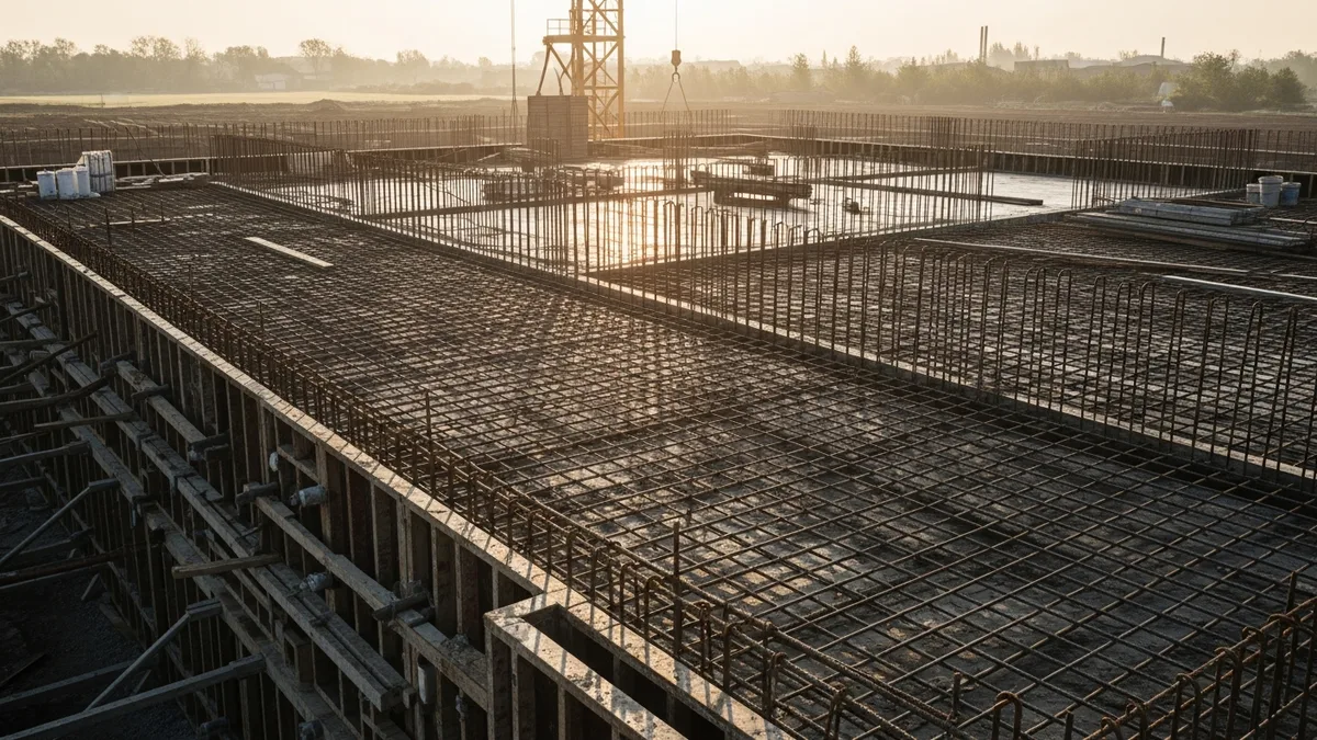
Step 4: Rebar Cage Placement
The reinforcing cage is assembled on site (or delivered pre-tied) and lowered into the shaft. Cages for large shafts can weigh several tons and require a crane for placement. Spacers or rollers attached to the cage maintain the required concrete cover between the steel and the hole wall. Cage placement needs to be done carefully to avoid disturbing the shaft walls or contaminating the bottom. For guidance on rebar detailing, check out our rebar placement and inspection guide.
Step 5: Concrete Placement
Read real contractor reviews and see why Projul carries a 9.8/10 on G2.
For dry shafts (no standing water), concrete can be placed by free-fall from the surface, provided the shaft is not so deep that the concrete segregates on the way down. Most specifications allow free-fall up to certain depths as long as the concrete does not hit the cage or shaft walls.
For wet shafts (filled with water or slurry), concrete is placed using a tremie pipe. The tremie extends to the bottom of the shaft, and concrete is pumped through it. As concrete rises, it displaces the slurry upward and out of the shaft. The tremie tip must stay submerged in the fresh concrete at all times to prevent mixing. This is where things get tricky, and where experience really matters.
The concrete mix design for drilled shafts is different from typical structural concrete. It needs high slump (usually 8 to 10 inches), extended working time, and good flow characteristics to fill around the cage without vibration. Your concrete mix design has to be right, or you will end up with defects.
Step 6: Casing Removal (if applicable)
If temporary casing was used, it gets pulled as the concrete level rises. Timing and technique matter here. Pull the casing too fast and you can create a neck in the shaft. Pull it too late and the concrete starts to set against the casing.
Inspection, Testing, and Quality Control
Deep foundations are buried. You cannot see the finished product the way you can with a footing or a slab. That makes quality control during installation absolutely critical.
During Installation
A geotechnical inspector should be on site for every shaft. They log soil conditions as drilling progresses, verify tip elevation, check bottom cleanliness, inspect the rebar cage before placement, and monitor concrete placement. If you are the GC, do not let the driller start a shaft without the inspector present. It is not worth the risk.
The inspector also watches concrete volumes. The theoretical volume of the shaft (based on diameter and depth) gets compared to the actual volume of concrete placed. If you place significantly more concrete than the theoretical volume, it means the hole is oversized (the soil caved or the drill wandered). If you place less, something is wrong, and the shaft may have a defect.
Post-Installation Testing
Several methods exist to check finished shaft integrity:
- Crosshole Sonic Logging (CSL): PVC access tubes are cast into the shaft during construction. After the concrete cures, a probe sends ultrasonic pulses between tubes to detect voids, inclusions, or poor-quality concrete. This is the most common integrity test for large-diameter shafts.
- Thermal Integrity Profiling (TIP): Temperature sensors measure the heat generated by curing concrete throughout the shaft. Anomalies in the temperature profile indicate potential defects. This method is gaining popularity because it can evaluate the full cross-section, including the concrete cover zone outside the cage.
- Static Load Testing: A test shaft is loaded to verify capacity. This is the most direct method but also the most expensive and time-consuming. It is typically reserved for large projects or when soil conditions are uncertain.
- Dynamic Testing and Rapid Load Testing: These methods apply a quick impact or push to the shaft head and measure the response. They are faster and cheaper than static tests but provide less definitive results.
Good scheduling is important here. Testing takes time, and results need to come back before you build on top of the foundations. Build your schedule with enough float for testing and potential remediation.
Common Problems and How to Avoid Them
Drilled shaft construction has a lot of ways to go sideways. Here are the issues that come up most often:
Caving and Soil Collapse
When the shaft walls collapse during drilling, soil falls into the hole and contaminates the concrete or reduces the shaft diameter. Prevention starts with reading the geotech report carefully and having casing or slurry ready before you need it. Do not assume a dry method will work just because it did on your last project. Every site is different.
Groundwater Problems
Unexpected groundwater can flood a shaft, contaminate concrete, or destabilize the walls. If the geotech report indicates water, plan for the wet method from the start. Trying to switch from dry to wet mid-shaft is messy and risky.
Bottom Sediment
Loose material at the shaft bottom reduces end-bearing capacity. This is especially problematic in slurry-filled shafts where cuttings settle during the time between drilling and concrete placement. Minimize the time between cleanout and concrete placement, and re-clean if there is a delay.
Rebar Cage Displacement
If the cage shifts during concrete placement, you lose cover on one side and may violate structural requirements. Use adequate spacers, handle the cage carefully during placement, and monitor its position throughout the pour.
Concrete Defects
Necking (reduced diameter), soft bottoms, inclusions of soil or slurry, and honeycombing can all occur if the concrete placement process goes wrong. The mix design, tremie technique, and casing removal sequence all have to work together. This is not a place to cut corners or use the cheapest ready-mix supplier.
If you are managing project costs on a deep foundation job, build contingency into your budget for potential shaft repairs. Even on well-run projects, one or two shafts out of a large group may need remediation.
Managing Drilled Shaft Projects: Tips for Contractors
Deep foundation work involves serious money, specialized equipment, and tight coordination between multiple parties. Here is how to keep things running smoothly:
Start with the Geotech
Read the full geotechnical report, not just the summary. Pay attention to the boring logs closest to your shaft locations. Look at the soil descriptions, blow counts, groundwater levels, and any notes about obstructions or unusual conditions. If something does not make sense, call the geotechnical engineer and ask. A 15-minute phone call can save you thousands in the field.
Before you even break ground, make sure you have reviewed the soil testing data thoroughly. This is the foundation of your foundation work, and surprises underground are the expensive kind.
Coordinate Access and Logistics
Drill rigs are big. The support equipment (cranes, concrete pumps, slurry plants, casing) takes up even more space. Plan your site layout carefully, especially on urban or confined sites. Think about where spoils will be stockpiled, how concrete trucks will access the shaft locations, and where the slurry recycling equipment will sit.
Sequence Your Work
On projects with many shafts, the drilling sequence matters. You generally do not want to drill adjacent shafts back-to-back because the vibration and ground disturbance from drilling one shaft can affect a freshly poured neighbor. Work out a sequencing plan with the driller and the engineer.
Track Everything
Every shaft should have a detailed installation log that records: drill start and finish times, soil conditions encountered at each depth, any changes from expected conditions, casing installation and removal, rebar cage details and placement, concrete volumes (theoretical vs. actual), concrete delivery tickets and test cylinders, and any problems encountered and how they were resolved.
This documentation protects you if questions come up later about shaft quality. Using construction project management software to track and store these records makes it much easier to stay organized, especially on projects with dozens or hundreds of shafts.
Budget Realistically
Drilled shaft costs vary widely based on diameter, depth, soil conditions, and location. Get detailed quotes from specialty subcontractors and make sure their pricing accounts for the specific conditions on your site. Watch out for unit price contracts that look cheap but have aggressive assumptions about production rates or soil conditions. A low bid that assumes dry-method drilling on a site with known groundwater issues is going to blow up in change orders.
Plan for Weather
Heavy rain can flood open shafts, delay concrete placement, and turn your site into a mud pit. Have a plan for dewatering, covering open shafts, and protecting freshly poured concrete. Build weather days into your construction schedule so you are not scrambling when the forecast turns bad.
Deep foundation work is one of those specialties where experience and preparation make the biggest difference between a smooth project and a disaster. Take the time to plan it right, hire qualified people, and do not skip the inspections. The structure sitting on top of those shafts is counting on every single one being built correctly.
Curious how this looks in practice? Schedule a demo and we will show you.
If you are looking for a better way to manage your foundation projects, including scheduling, cost tracking, and field documentation, Projul gives you the tools to keep complex jobs organized from bid to closeout.
Frequently Asked Questions
What is the difference between a caisson and a drilled shaft?
How deep can a drilled shaft foundation go?
When should I use a drilled shaft instead of a spread footing?
How long does it take to install a drilled shaft?
What diameter are most drilled shaft foundations?
Related Articles
Construction Geotextile and Erosion Control Fabric Guide
Geotextile fabric shows up on nearly every construction project, from silt fence along the perimeter to separation...
Read More →
Construction Backfill Compaction Testing and Methods Guide
Backfill compaction is one of those things that separates a solid project from a callback nightmare. This guide covers...
Read More →
Construction Grout and Mortar Types Selection Guide
Picking the wrong grout or mortar can wreck a project. This guide breaks down every major type, when to use each one,...
Read More →