Structural Welding Inspection in Construction: CWI Roles, Weld Types, and Acceptance Criteria | Projul
Structural welding is where steel construction either comes together properly or falls apart, sometimes literally. Every beam-to-column moment connection, every column splice, and every brace connection depends on welds that meet strict quality standards. When those welds are done right and properly inspected, the structure performs as designed. When they are not, the consequences range from costly repairs to catastrophic failure.
This guide walks contractors through the structural welding inspection process from start to finish. Whether you are a steel erector, a general contractor managing steel subcontractors, or a welding contractor looking to tighten up your quality program, understanding how welding inspection works will help you keep projects on schedule and out of trouble.
Why Structural Welding Inspection Matters
Structural welds carry loads that hold buildings, bridges, and industrial structures together. Unlike a bolt that can be visually verified and torque-checked, a weld’s quality depends on what is happening inside the joint, below the surface where you cannot see it. Internal defects like lack of fusion, slag inclusions, and cracks can exist in a weld that looks perfectly fine on the outside.
This is why the building code requires independent inspection of structural welding. The International Building Code (IBC) references AWS D1.1 Structural Welding Code for steel buildings and requires special inspection by qualified individuals. The inspector is the last line of defense between a defective weld and a loaded structure.
The Governing Standard: AWS D1.1
AWS D1.1, published by the American Welding Society, is the primary standard for structural steel welding in building construction. It covers everything from welder qualifications and welding procedure specifications to inspection requirements and acceptance criteria.
Key sections that every contractor should be familiar with:
Section 3: Prequalification of WPSs. Defines which welding procedures can be used without separate qualification testing based on established parameters.
Section 4: Qualification. Covers welder performance qualification testing, WPS qualification by testing, and the rules for maintaining qualification.
Section 5: Fabrication. Details requirements for joint preparation, fit-up, welding technique, preheat, and workmanship.
Section 6: Inspection. Specifies visual inspection criteria, NDT methods and acceptance criteria, and inspector qualification requirements.
Section 8: Strengthening and Repair. Covers procedures for repairing defective welds and modifying existing structures.
For seismic applications, AWS D1.8 Seismic Supplement adds additional requirements for connections in the seismic force-resisting system. These requirements are more stringent than standard D1.1 provisions.
Roles and Responsibilities
The Contractor’s Quality Control (QC) Inspector
The steel fabricator and erector are responsible for their own quality control program. This includes having qualified QC inspectors who verify weld quality before presenting work for acceptance inspection. QC inspection catches problems early when they are cheapest and easiest to fix.
The Owner’s Quality Assurance (QA) Inspector
The QA inspector, often a third-party inspection firm hired by the owner or engineer, provides independent verification that welding meets the contract requirements. This is the special inspector referenced in the building code. The QA inspector does not direct the contractor’s work but rather verifies that the finished product meets the standard.
The Engineer of Record
The structural engineer specifies weld types, sizes, and any special inspection requirements on the drawings and in the project specifications. The engineer also reviews NDT reports and makes decisions on weld repairs when needed.
The Welder
Every welder performing structural work must be qualified per AWS D1.1 Section 4. Qualification is specific to welding process, position, and material thickness range. A welder qualified for flat-position groove welds is not automatically qualified for overhead work. Keeping welder qualification records organized and current is a basic requirement that too many contractors struggle with.
Types of Structural Welds
Groove Welds
Groove welds join members along their edges using various joint preparations. They come in two categories.
Complete Joint Penetration (CJP): The weld extends through the full thickness of the joint. CJP welds develop the full strength of the connected members. They are required for moment connections, splices in tension members, and other critical joints.
Partial Joint Penetration (PJP): The weld extends only partway through the joint. PJP welds have a defined effective throat dimension that determines their capacity. They are used where full member strength is not required at the connection.
Common groove weld joint preparations include single-V, double-V, single-bevel, double-bevel, single-J, and single-U configurations. The joint preparation specified depends on material thickness, access for welding, and whether backing is used.
Fillet Welds
Fillet welds are the most common weld type in structural steel construction. They are roughly triangular in cross-section and join members at approximately right angles, such as web-to-flange connections, stiffener plates, and gusset plates. Fillet weld size is specified as the leg dimension, and the effective throat is calculated from the leg size.
Flare Groove Welds
Used to join curved surfaces, such as round HSS members to flat plates. The effective throat dimension depends on the member radius and welding position.
Pre-Weld Inspection
Good inspection starts before the arc is struck. Pre-weld checks verify that conditions are right for producing quality welds.
Fit-Up Verification
The inspector checks joint fit-up against the WPS and AWS D1.1 requirements. This includes:
- Root opening (gap between members)
- Groove angle
- Root face dimension
- Alignment and offset between members
- Backing bar fit, if used
- Cleanliness of joint surfaces
Fit-up tolerances are tight. For prequalified CJP groove welds, root opening tolerances are typically plus or minus 1/16 inch from the specified dimension. Out-of-tolerance fit-up must be corrected before welding or addressed with an alternate procedure approved by the engineer.
Material Verification
Confirm that base metals and filler metals match the WPS requirements. Check mill test reports (MTRs) for base metal and certificates of conformance for filler metals. Verify that electrodes and fluxes are properly stored per manufacturer recommendations, especially low-hydrogen electrodes that are sensitive to moisture pickup.
Preheat Verification
Check that preheat has been applied correctly before welding begins. Use a temperature-indicating crayon, infrared thermometer, or thermocouple to verify the minimum preheat temperature at the required distance from the joint (typically 3 inches in all directions from the point of welding).
Preheat requirements depend on base metal type, thickness, and the welding process being used. AWS D1.1 Table 3.2 provides minimum preheat temperatures for prequalified procedures. Thicker and higher-carbon materials require higher preheat temperatures to prevent hydrogen-induced cracking.
Welder Qualification Verification
Confirm that each welder assigned to the work holds current qualification for the welding process, position, and material thickness they will be performing. Review qualification test records. If a welder has not used a specific process for six months or more, requalification may be required per AWS D1.1 provisions.
During-Weld Inspection
Monitoring welding operations in progress allows the inspector to catch technique problems before they create defects.
Key Observations
- Welding parameters (amperage, voltage, travel speed) within WPS range
- Proper interpass temperature maintained (not exceeding maximum)
- Correct stringer bead or weave technique per WPS
- Adequate interpass cleaning between weld layers
- Proper electrode handling and storage
- Wind protection for gas-shielded processes (maximum 5 mph at the weld)
- Back-gouging and preparation of backside for double-sided welds
Common Process Issues
SMAW (Stick Welding): Watch for improper electrode angle, excessive arc length, and failure to remove slag between passes. Low-hydrogen electrodes (E70XX) must be kept in heated ovens or hermetically sealed containers until use.
FCAW (Flux-Cored Arc Welding): Check gas flow rates, contact tip condition, and wire feed speed. Self-shielded FCAW does not use gas but is sensitive to technique parameters.
GMAW (MIG Welding): Verify shielding gas type and flow rate. GMAW is highly sensitive to wind and drafts that can disrupt gas coverage.
SAW (Submerged Arc Welding): Used mainly in shop fabrication for long, straight welds. Monitor flux depth and recovery, wire alignment, and travel speed.
Visual Inspection of Completed Welds
Visual inspection (VT) is required on 100% of structural welds. It is the most basic and most important inspection method. A skilled CWI can identify most weld defects through careful visual examination.
What the Inspector Checks
Weld size: Using fillet weld gauges and measurement tools, verify that the weld meets the specified size on the drawings. Undersized welds are the most common defect found in structural steel construction.
Weld profile: The weld face should have proper convexity or flatness. Excessive convexity creates stress concentrations. Excessive concavity reduces the effective throat. Overlap (weld metal spilling over the toe without fusing to the base metal) is a defect that must be repaired.
Undercut: A groove melted into the base metal at the toe of the weld. AWS D1.1 limits undercut depth based on the loading condition, typically 1/32 inch for most applications.
Porosity: Visible surface pores. Scattered porosity within the acceptance limits of AWS D1.1 Table 6.1 is acceptable. Clustered or linear porosity usually indicates a process problem.
Cracks: Any crack, regardless of size or location, is a rejectable defect under AWS D1.1. Cracks in structural welds are never acceptable.
Arc strikes: Stray arc marks on the base metal outside the weld joint create hard spots that can initiate cracks. They must be ground smooth and examined.
Spatter: While not a structural defect, excessive spatter indicates process problems and may need to be removed per the specification.
Weld length and location: Verify that welds are in the correct locations and have the required lengths per the drawings.
Non-Destructive Testing (NDT)
When visual inspection alone is not sufficient to verify weld quality, NDT methods examine the internal structure of completed welds.
Ultrasonic Testing (UT)
UT uses high-frequency sound waves to detect internal defects. A transducer sends sound waves into the weld, and reflections from defects are displayed on a screen. UT is the most common NDT method for structural steel CJP groove welds. It can detect cracks, lack of fusion, slag inclusions, and incomplete joint penetration.
UT requires a qualified technician (typically ASNT Level II or III) and is performed per AWS D1.1 Section 6 acceptance criteria. Results are documented on UT report forms that record defect location, size, and indication rating.
Magnetic Particle Testing (MT)
MT detects surface and near-surface defects by magnetizing the weld area and applying iron particles that collect at defect locations. It is commonly used for fillet weld inspection, repair weld verification, and inspection of weld access holes in moment connections.
MT is faster and less expensive than UT but can only detect defects at or very near the surface.
Radiographic Testing (RT)
RT uses X-rays or gamma rays to produce an image of the weld’s internal structure on film or a digital detector. It provides a permanent record of weld quality but is less practical for field use due to radiation safety requirements. RT is more common in piping and pressure vessel work than in structural steel building construction.
Penetrant Testing (PT)
PT detects surface-breaking defects by applying a liquid penetrant that seeps into cracks and pores. After cleaning the excess, a developer draws the penetrant out of defects, making them visible. PT works on non-magnetic materials where MT cannot be used, such as stainless steel or aluminum structural members.
Common Weld Defects and Their Causes
Cracks
The most serious weld defect. Cracks can occur in the weld metal, in the heat-affected zone (HAZ) of the base metal, or in the base metal itself.
Hot cracks form during solidification and are caused by high restraint, improper joint design, or contamination.
Cold cracks (hydrogen-induced cracks) form hours or days after welding when hydrogen trapped in the weld migrates and causes delayed cracking. Prevention requires proper preheat, low-hydrogen filler metals, controlled interpass temperature, and sometimes post-weld heat treatment.
Lack of Fusion
Occurs when the weld metal does not properly fuse to the base metal or to previously deposited weld metal. Caused by insufficient heat input, improper technique, or contaminated joint surfaces. Lack of fusion is difficult to detect visually and typically requires UT or RT to identify.
Incomplete Joint Penetration
The weld does not extend through the full joint thickness on a CJP weld. Causes include insufficient root opening, excessive root face, wrong groove angle, or inadequate heat input. Like lack of fusion, this defect often requires NDT to detect.
Slag Inclusions
Non-metallic material trapped in the weld metal, typically slag from SMAW or FCAW processes. Caused by inadequate interpass cleaning, improper technique, or erratic travel speed. Small isolated inclusions may be acceptable per AWS D1.1. Linear or clustered inclusions require repair.
Porosity
Gas pores in the weld metal caused by contamination, moisture, inadequate shielding gas coverage, or excessive wind. Scattered porosity within code limits is acceptable. Piping porosity (elongated gas channels) and clustered porosity are rejectable.
Weld Repair Procedures
When inspection reveals rejectable defects, the weld must be repaired. AWS D1.1 requires that repair procedures follow a defined process.
- Mark the defect location clearly
- Remove the defective weld metal using grinding, air carbon arc gouging, or machining
- Prepare the repair joint to a suitable profile for re-welding
- Verify the repair joint preparation by visual and, if required, MT inspection
- Re-weld using a qualified WPS
- Re-inspect the repair weld using the same inspection methods required for the original weld
Repeated repairs in the same location require engineer approval and may require additional preheat or post-weld heat treatment to manage accumulated residual stresses.
Seismic Welding Requirements
Structures in higher seismic design categories face additional welding requirements under AWS D1.8 and AISC 341.
Demand critical welds in the seismic force-resisting system require filler metals with minimum Charpy V-notch toughness. This ensures the weld metal can absorb energy without brittle fracture during seismic loading.
Weld access holes in beam-to-column moment connections must meet specific geometry and surface finish requirements. They must be inspected by MT after cutting.
Protected zones on beams near moment connections prohibit welded attachments, arc strikes, and other discontinuities that could initiate fracture during seismic events.
NDT requirements for seismic welding are typically more extensive. Many specifications require 100% UT of CJP welds in moment connections.
Documentation
Proper documentation is not optional. It is a code requirement and a liability protection measure.
Required Records
- Welder qualification certificates
- Welding Procedure Specifications (WPS) and supporting PQRs
- Visual inspection reports
- NDT reports (UT, MT, RT, PT as applicable)
- Preheat and interpass temperature records
- Repair and re-inspection documentation
- Material certifications (MTRs and filler metal certificates)
Record Retention
Most specifications require retention of welding inspection records for the life of the structure. Keep organized digital copies in addition to paper records.
How Projul Helps Manage Welding Inspection
Tracking welder qualifications, WPS documents, inspection reports, NDT results, and repair logs across multiple connections on a steel building is a documentation-heavy process that can quickly become disorganized. Projul’s construction project management software gives contractors a central location to store and retrieve inspection records, track which connections have been completed and inspected, and coordinate with QA inspectors and engineers without losing paperwork between the field trailer and the office.
Final Thoughts
Structural welding inspection is not a box to check on a compliance form. It is a critical quality assurance process that protects the safety of everyone who will occupy or use the structure you are building. Understanding the inspection process, keeping your welders qualified and well-equipped, maintaining clean and organized documentation, and treating your CWI as a partner rather than an obstacle will keep your steel projects running smoothly and your welds passing inspection the first time.
The contractors who consistently do well with welding inspection are the ones who invest in quality control before the QA inspector ever shows up. Get your fit-up right, verify your preheat, use the correct electrodes, and inspect your own work before calling for acceptance inspection. That approach saves time, saves money, and builds a reputation that wins more structural steel contracts.
Frequently Asked Questions
What is a CWI and when is one required?
What is the difference between a complete joint penetration weld and a partial joint penetration weld?
How do you know if a weld passes visual inspection?
What is a Welding Procedure Specification?
When is ultrasonic testing required on structural welds?
What causes porosity in structural welds?
Can a welder work on structural steel without certification?
What is preheat and why does it matter?
Related Articles
BIM Clash Detection: How to Catch Conflicts Before They Cost You on the Jobsite
BIM Clash Detection: How to Catch Conflicts Before They Cost You on the Jobsite Every contractor has a story about the...
Read More →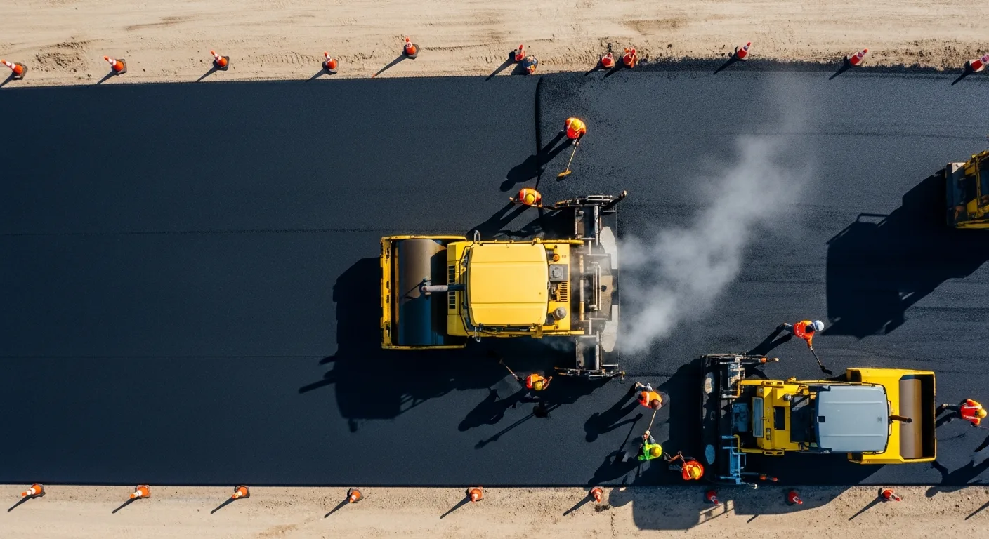
Asphalt Paving and Compaction Guide: Mix Types, Laydown Temperatures, and Quality Testing
Asphalt paving looks straightforward from a distance. A truck dumps material, the paver lays it down, and rollers...
Read More →
Construction Jobsite Wi-Fi & Connectivity Guide: Setting Up Reliable Internet in the Field
A practical guide to getting reliable internet on construction job sites. Learn about cellular hotspots, mesh networks,...
Read More →